Some will ask why do this when the wii already has gc controller ports. Well this mod is primarily for use on the Wii U because it lacks gc controller ports.
Now with that out of the way. Lets make one of these:
![IMG_20121221_180324_zps3af7ce1e.jpg]()
Out of these:
![IMG_20121221_122008_zps7232bfdd.jpg]()
So once these two pads are acquired, open them up. You'll need a triwing screw driver.
![IMG_20121221_122607_zps3d8c7127.jpg]() \
\
There's some things we will need to do to both pads before we start wiring them up. Lets start with the GC pad first.
Lets remove the rumble motor.
![IMG_20121221_131538_zps554f2635.jpg]()
Dremel down flat the plastic that was holding the rumble motor.
![IMG_20121221_132838_zpsa9833360.jpg]()
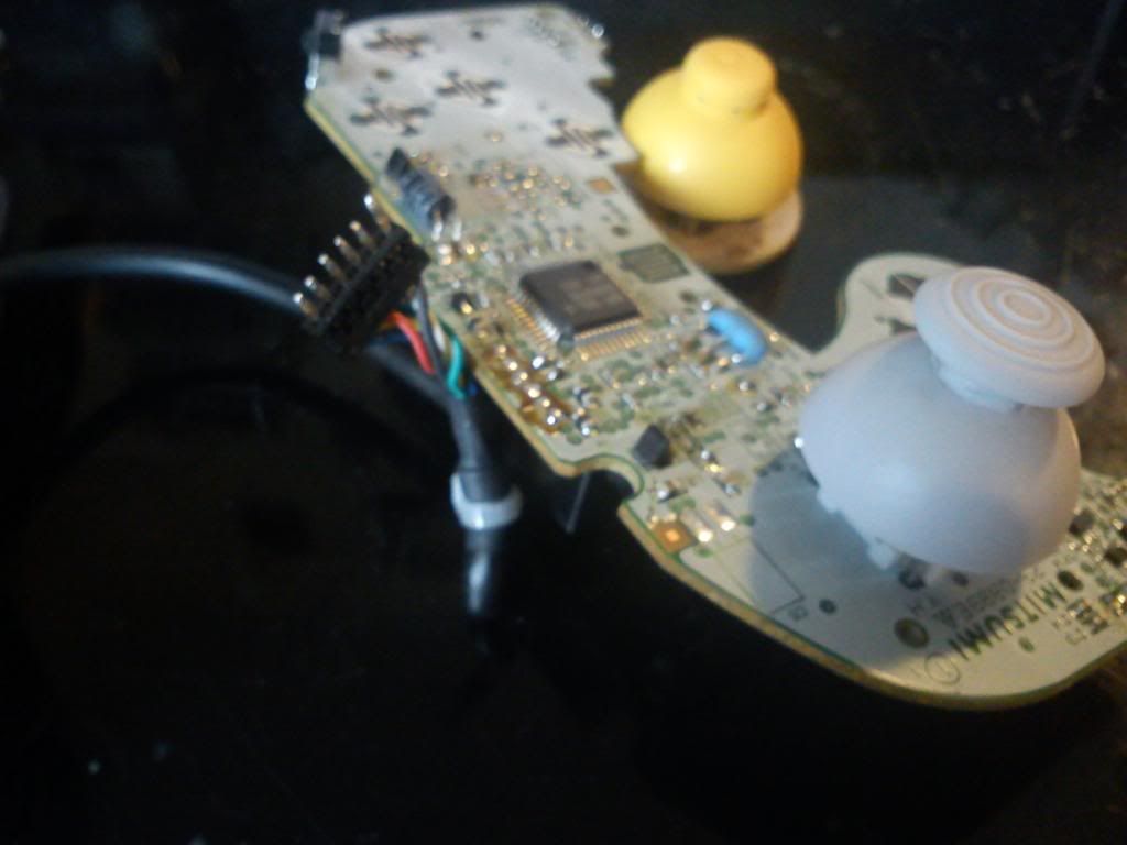
Desolder the gc cable.
![IMG_20121221_132149_zps5d462220.jpg]()
Dremel off the IC using a cutting wheel.
![IMG_20121221_133151_zps39d5346d.jpg]()
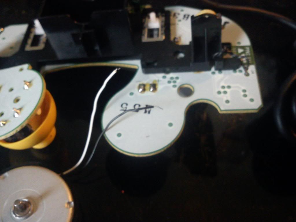
Using the dremel again, cut lines around the spot where the gc cable was attached at. Also go ahead and clean up the contact pads of the IC by desoldering off the remaining cut off IC pins.
![IMG_20121221_134145_zps13e60d2b.jpg]()
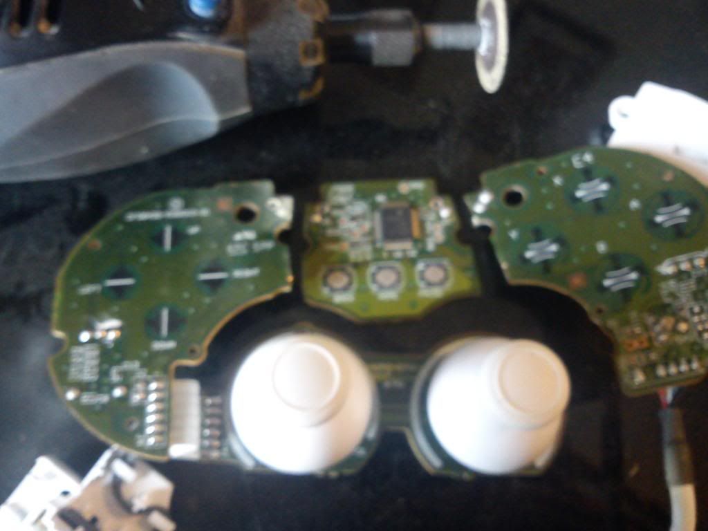
Now lets work on the classic controller pcb.
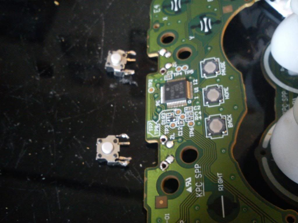
Desolder off the ZL and ZR switches.
![IMG_20121221_134649_zpsd93f5448.jpg]()
Use the dremel to cut the pcb. Follow the pink line.
![Untitled4_zps2089b2ff.png]()
![IMG_20121221_135108_zpsbd8300a5.jpg]()
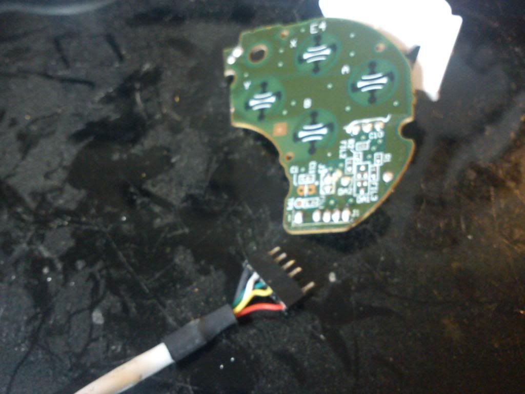
Desolder the cable like you did for the gc pad.
![IMG_20121221_135552_zpsabc15233.jpg]()
Now take that same cable and solder to the gamecube controller where it's cable used to be. Bridge the pins for the white wire and black wire with solder.
![IMG_20121221_141925_zps56f0c180.jpg]()
Lets start on some wiring now.
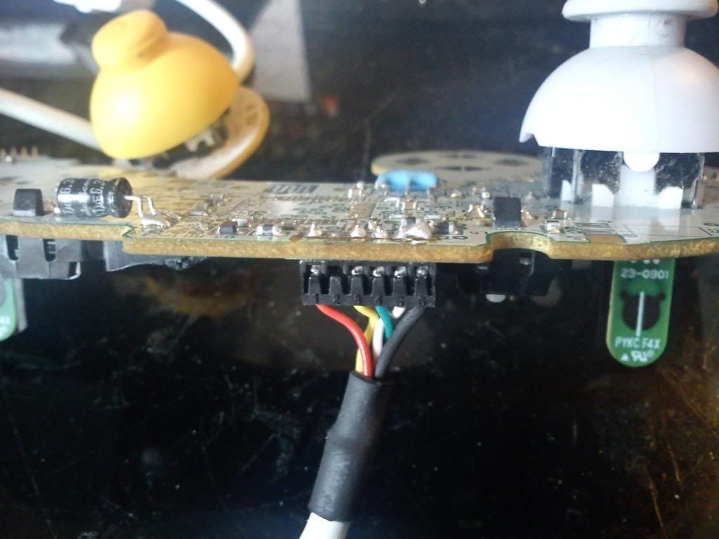
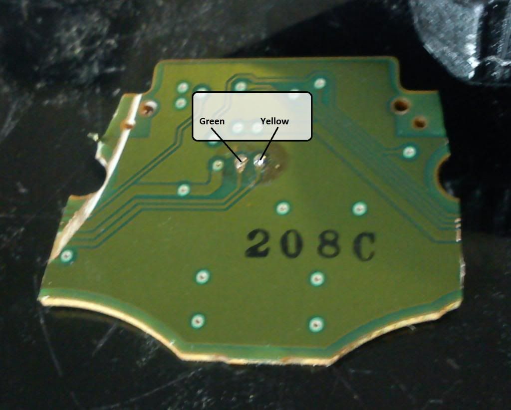
On the bottom of the cut up classic controller are two vias that will be wired up. These will be the only things soldered on the bottom. You'll need to scrape away the surface with a blade. The labels are for which color of the classic controller cable they will be wired up to. The wiring used throughout this mod is 30 guage wire.
![IMG_20121221_141228_zpsd15a5a27.jpg]()
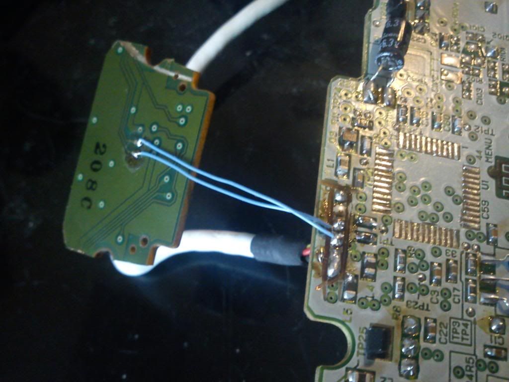
![IMG_20121221_145808_zpsf44e38c5.jpg]()
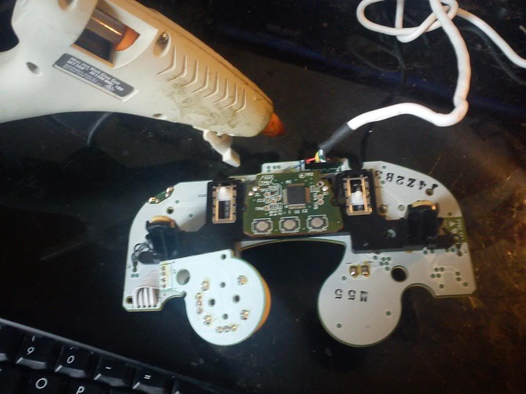
After the bottom side of the pcb is wired up, hot glue the pcb to the gamecube pad. Place it in between the two trigger sliders where the rumble motor holder was dremeled.
![IMG_20121221_150023_zpsb73b76c2.jpg]()
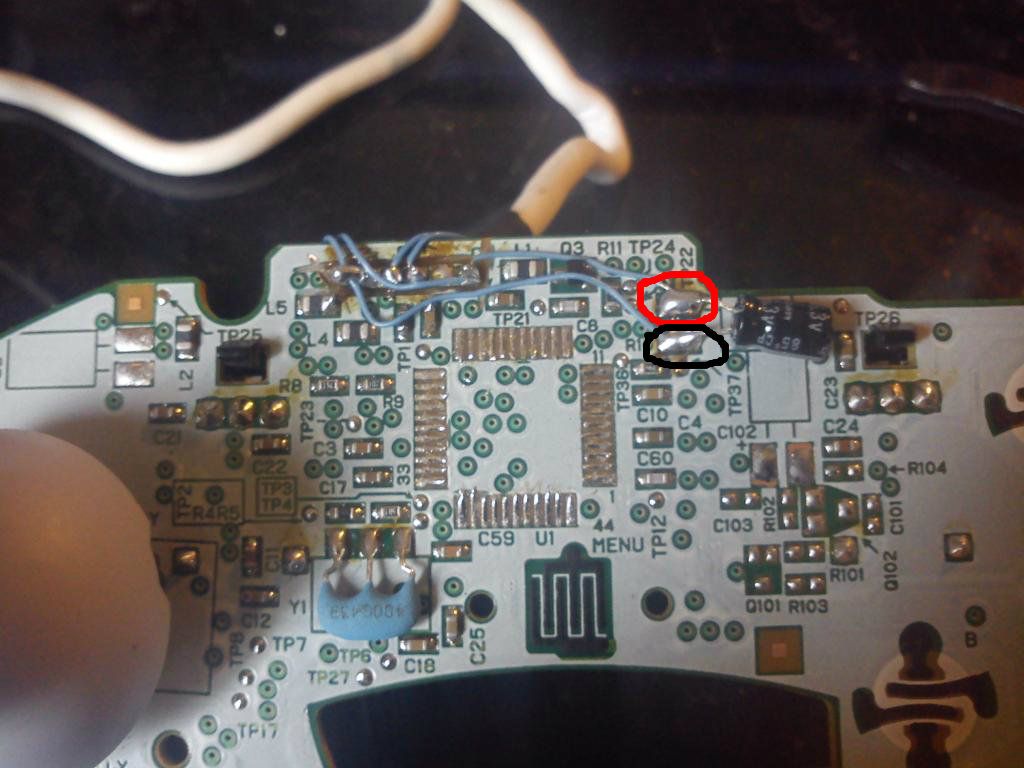
Solder a wire from the spot with the black circle to the pin that has the black wire. Solder a wire from the spot with the red circle to the pin that has the red wire.
![IMG_20121221_151116_zpsbb0640a6.jpg]()
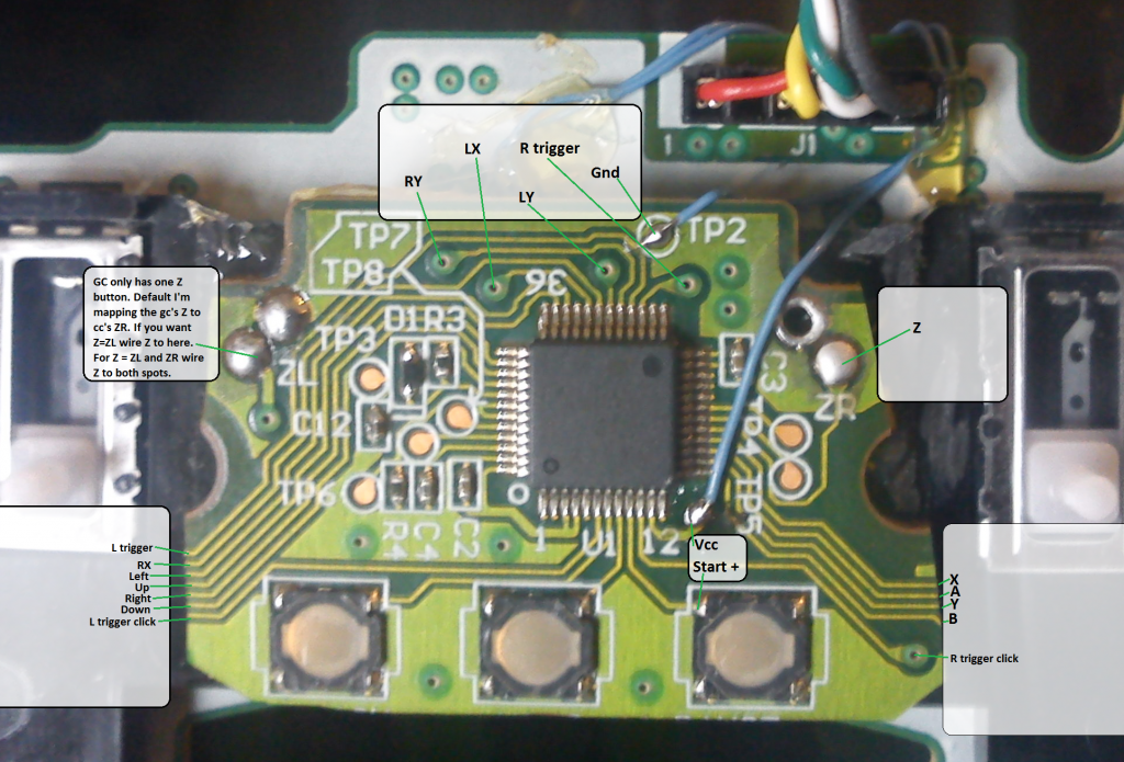
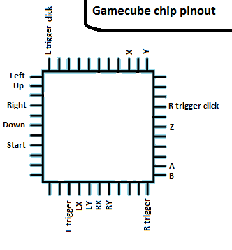
This is were things get very hard. All these labeled spots need to be wired up to the gamecube pad where the IC was (Vcc and Gnd can be wired to the pins of the red and black wire like in the previous picture).
![Untitled3_zps6efaffc6.png]()
![Untitled2_zps53889a68.png]()
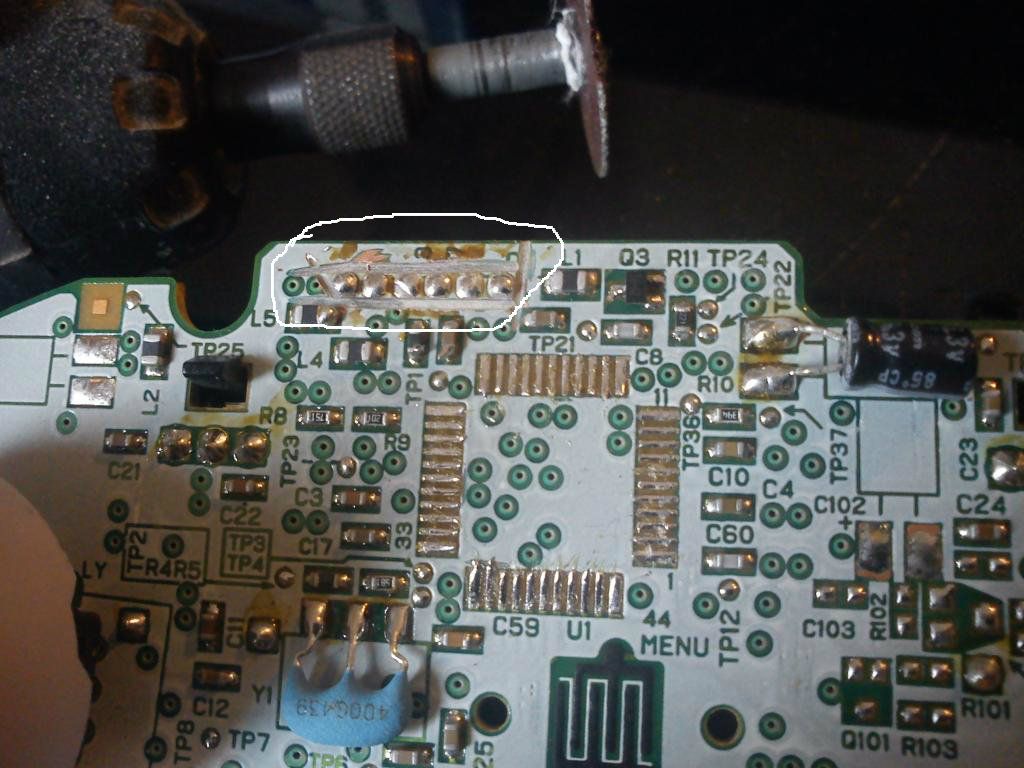
I'm not going to go through each and every trace and via you'll need to wire up in the diagram, but I'll show one.
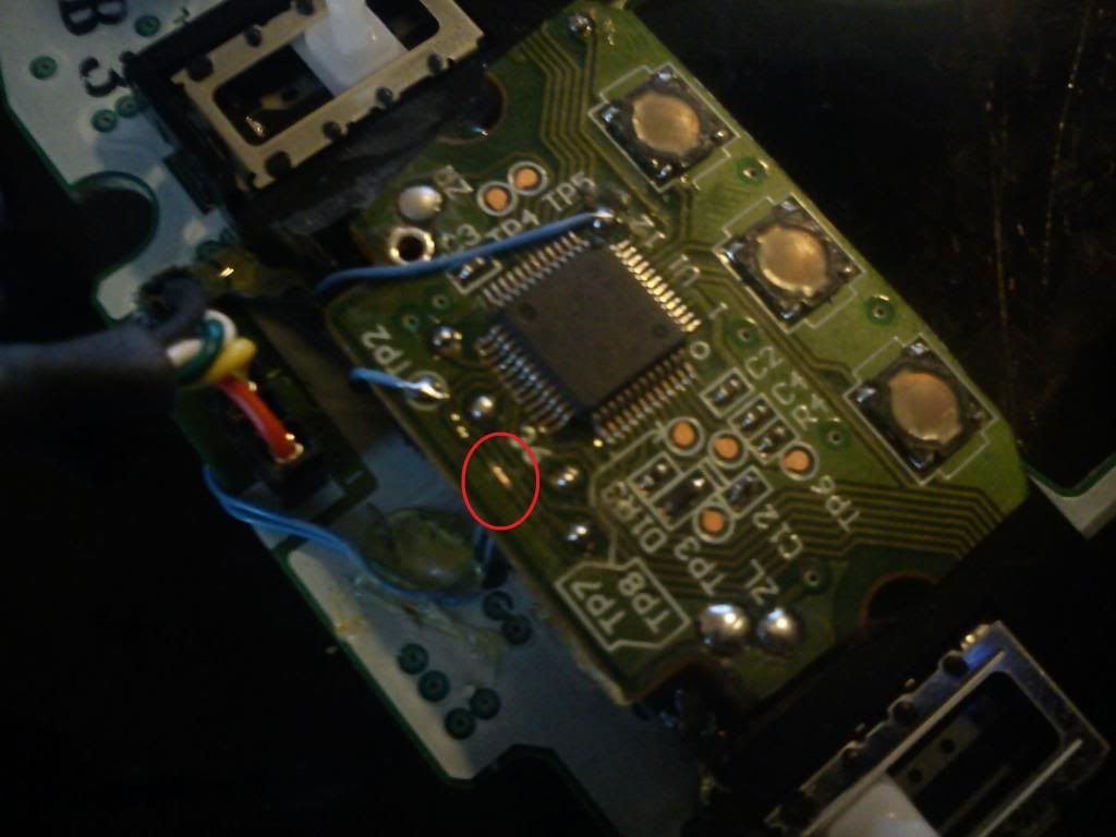
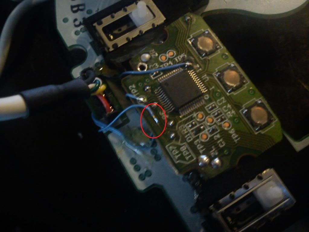
The circled trace here is for the L trigger. Using the pinout provided you can follow the traces to find suitable spots to wire up at. Using a blade I scraped off the surface of the trace to expose the copper trace. Then tin the exposed trace and a wire with some solder. Then you can solder the wire to the trace and apply a little hot glue on the wire to keep it secure in place. Solder the other end of the wire to the corresponding location on the gc pad where the IC was.
![IMG_20121221_162814_zps912d7f20.jpg]()
![IMG_20121221_163144_zps9c537590.jpg]()
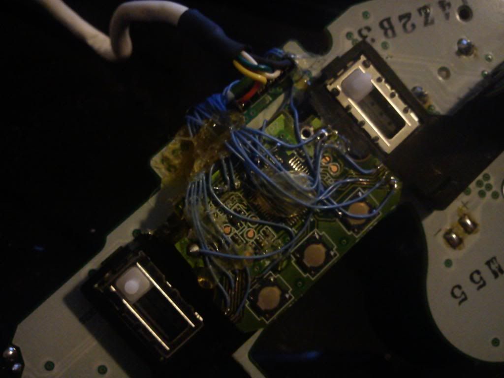
Classic Controller pcb all wired up:
![IMG_20121221_180023_zpsb9948b7f.jpg]()
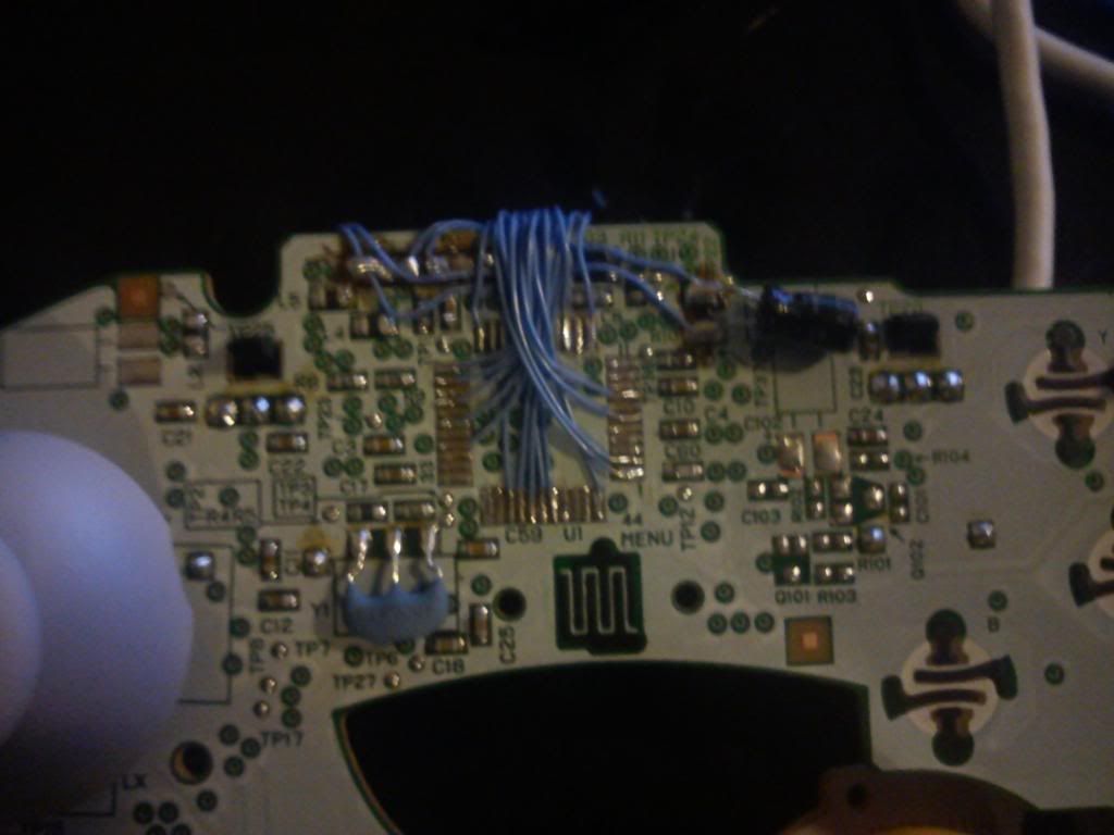
Gamecube side all wired up:
![IMG_20121221_175952_zpsd295611c.jpg]()
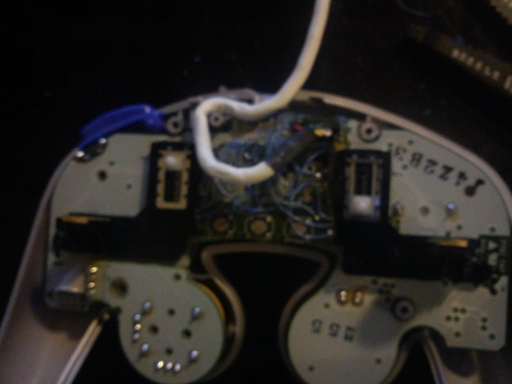
With the hard part all done, place the board back into the gamecube shell. Position the cable through the strain relief stems like so and close up the pad.
![IMG_20121221_180127_zps2c782658.jpg]()
Plug into a WiiMote and enjoy!
![IMG_20121221_180324_zps3af7ce1e.jpg]()
Now with that out of the way. Lets make one of these:

Out of these:
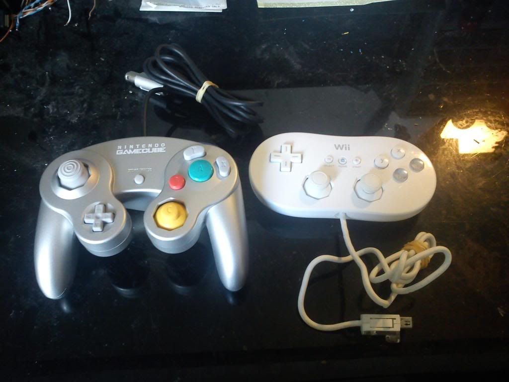
So once these two pads are acquired, open them up. You'll need a triwing screw driver.
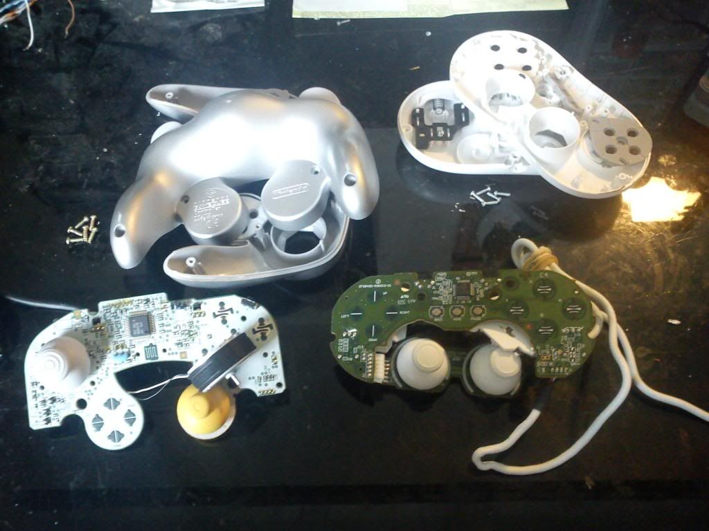 \
\There's some things we will need to do to both pads before we start wiring them up. Lets start with the GC pad first.
Lets remove the rumble motor.
Dremel down flat the plastic that was holding the rumble motor.

Desolder the gc cable.
Dremel off the IC using a cutting wheel.

Using the dremel again, cut lines around the spot where the gc cable was attached at. Also go ahead and clean up the contact pads of the IC by desoldering off the remaining cut off IC pins.
Now lets work on the classic controller pcb.
Desolder off the ZL and ZR switches.
Use the dremel to cut the pcb. Follow the pink line.

Desolder the cable like you did for the gc pad.
Now take that same cable and solder to the gamecube controller where it's cable used to be. Bridge the pins for the white wire and black wire with solder.
Lets start on some wiring now.
On the bottom of the cut up classic controller are two vias that will be wired up. These will be the only things soldered on the bottom. You'll need to scrape away the surface with a blade. The labels are for which color of the classic controller cable they will be wired up to. The wiring used throughout this mod is 30 guage wire.
After the bottom side of the pcb is wired up, hot glue the pcb to the gamecube pad. Place it in between the two trigger sliders where the rumble motor holder was dremeled.
Solder a wire from the spot with the black circle to the pin that has the black wire. Solder a wire from the spot with the red circle to the pin that has the red wire.
This is were things get very hard. All these labeled spots need to be wired up to the gamecube pad where the IC was (Vcc and Gnd can be wired to the pins of the red and black wire like in the previous picture).
I'm not going to go through each and every trace and via you'll need to wire up in the diagram, but I'll show one.
The circled trace here is for the L trigger. Using the pinout provided you can follow the traces to find suitable spots to wire up at. Using a blade I scraped off the surface of the trace to expose the copper trace. Then tin the exposed trace and a wire with some solder. Then you can solder the wire to the trace and apply a little hot glue on the wire to keep it secure in place. Solder the other end of the wire to the corresponding location on the gc pad where the IC was.
Classic Controller pcb all wired up:
Gamecube side all wired up:
With the hard part all done, place the board back into the gamecube shell. Position the cable through the strain relief stems like so and close up the pad.
Plug into a WiiMote and enjoy!